
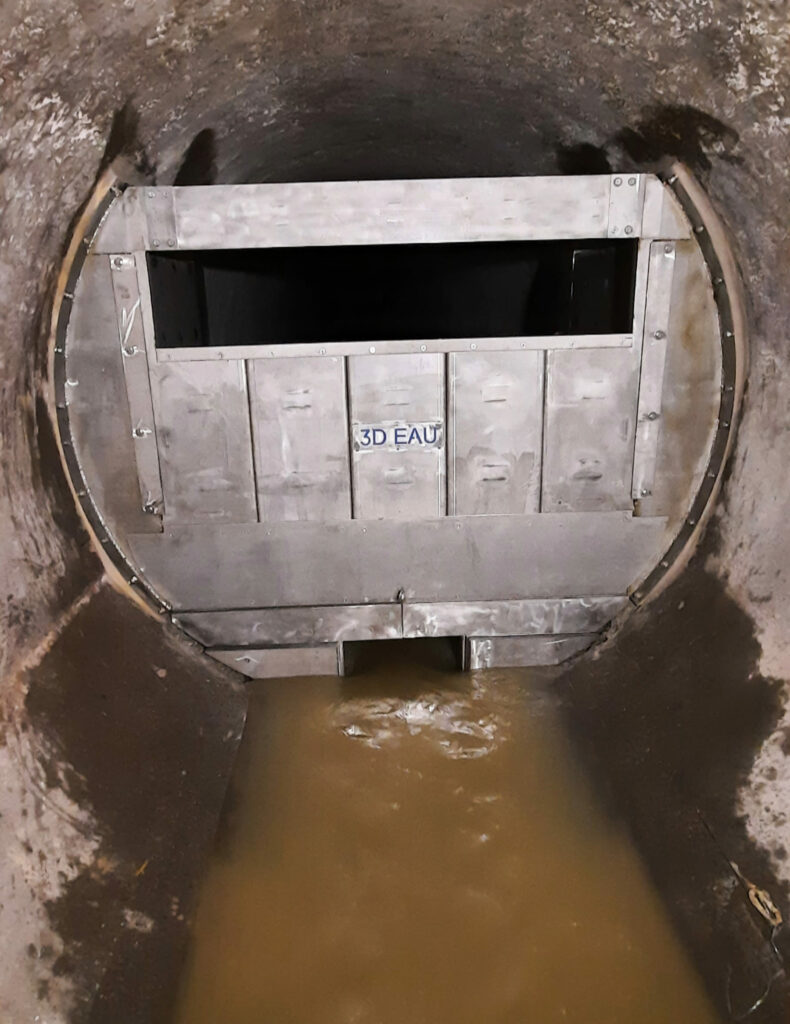
Self-regulating flow control gates: Reducing sewer overflow discharges
Since 2020, 3D EAU has designed and delivered in-network storage solutions using self-regulating hydrodynamic gates. A made-to-measure approach that reduces discharges into the natural environment without the need to build new stormwater retention basins.
The challenge
How can sewer overflow discharges into the natural environment be reduced by tapping into a network's existing capacity?
The proper operation of a wastewater treatment system can be assessed through the direct discharges of wastewater into the natural environment. Reducing these discharges is therefore a major challenge. Exploiting the storage capacity of wastewater collectors is an alternative to building stormwater tanks.
The 3D EAU solution
The self regulating flow control gate
Two configurations to maximise storage capacity
A regulating gate is a hydro-mechanical device installed directly inside a sewer collector to control the flow released downstream, based on the upstream water level. Unlike an electronically driven motorised valve, it operates entirely passively. A mechanical flap opens and closes automatically according to water level, with no electricity, no sensors, and no external control loop involved.
Across a network, these gates can be positioned in two complementary configurations, which can be combined within the same catchment area to maximise the storage capacity that can be mobilised, as shown in the animation. The regulating gate is installed directly in the collector for in-line storage.
The fuse gate is installed between an overflow point and the receiving environment. It acts as a movable riser on combined sewer overflow weirs.
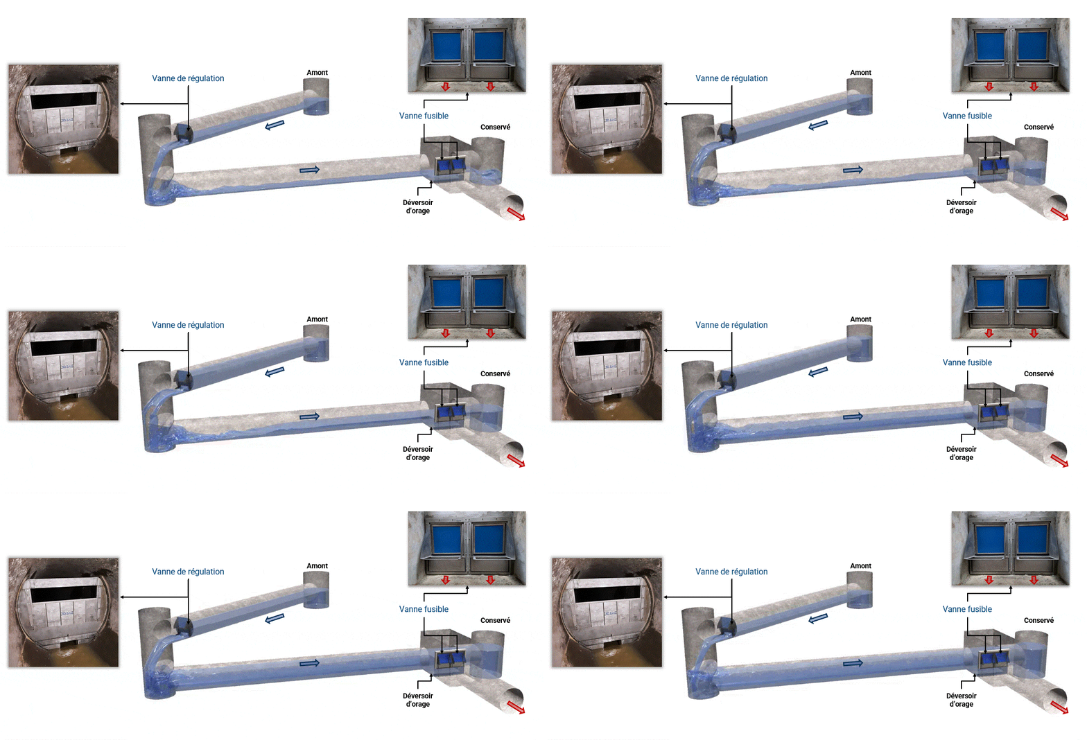
Self regulating flow control gate
The gates have no impact on dry-weather operation: a bottom orifice is sized to pass peak dry-weather flow without affecting the water surface profile; preserving the collector’s self-cleansing velocity, treatment continuity, and sediment load.
During light rainfall, the gate stays closed, regulating the volume flowing to the treatment plant. For heavier events, the gate opens progressively to maximise storage for as long as possible, before opening fully to restore the network’s full discharge capacity and prevent any surface flooding.
Deomatic Tilting Fuse Gate
In combined sewer overflow structures, these gates are positioned on the crest of the weir.
Acting as a raised threshold for the first overflow spills, the gate stores excess volumes in the network for rain events where the water level in the collector stays below a tilting threshold. Beyond that threshold, the gate opens fully, restoring the network’s discharge capacity, and no longer affects its operation. It closes again once the upstream water level drops back down to the height of its rotation axis.
How the self-regulating flow control gate works — Cross-Section View
Test how this gate works by adjusting the upstream water level with the slider below.
The self-regulating control gate in operation on site
How the Deomatic fuse gate works — Cross-Section View
Move the slider forward to see a complete storage cycle with no downstream backwater influence.
The Deomatic tilting fuse gate in operation on site
A six-step approach, led with the project owner
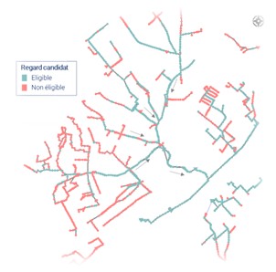
Eligibility study
This first step consists of:
- Assessing whether the network is suitable for a storage function.
- Identifying eligible collectors.
A network map showing the collectors that are candidates for a storage function.
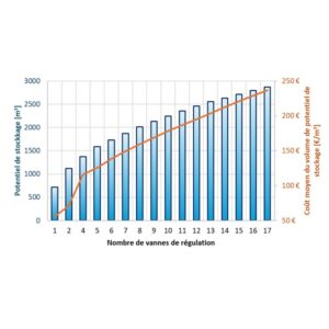
Gate positioning
Determining the number of gates through a Pareto-type analysis to optimise the cost/efficiency ratio, avoiding a solution that costs more than a conventional storage basin.
Hydraulic dimensioning
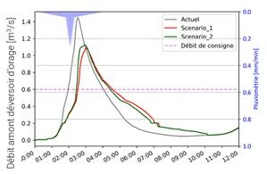
Working with the project owner, our engineers size the structures and validates their performance against a representative annual rainfall record, while guaranteeing no increase in flood risk for a reference storm event.
The solution is compared against an equivalent-performance storage basin for a relevant financial assessment.
Final design study
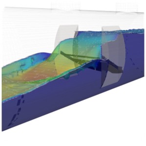
- Using CFD and a structural study, accounting for the geometric and hydraulic specifics of each site.
- SolidWorks drawings: breaking the structure down into transportable parts that fit through manholes.
- Bench testing to validate opening and closing heights.
Manufacturing and installation of the self regulating flow control gates
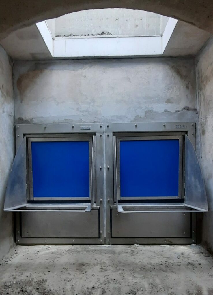
The gates are designed and made to measure in stainless steel in our workshops in France.
3D EAU bench-tests each gate to validate its hydraulic performance before delivering it to site for installation.
The control gates are installed without trenches and in just a few days, with a minimum of civil engineering work. The gates are lowered through the existing access manhole and installed in the network.
Instrumentation
- The solution is designed to measure flow using sensors (height, inclinometers) integrated into a supervision system.
- Calibration using CFD is possible to ensure high measurement accuracy, taking into account the specific hydraulic and geometric characteristics of the site.
Maintaining self-regulating flow control gates
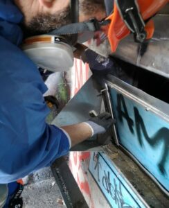
The system benefits from simplified maintenance (gaskets to be replaced roughly every 3 years, the only consumable part), keeping operating costs low. Maintenance can be carried out by 3D EAU under a service contract.
Pourquoi choisir les vannes de stockage en réseau 3D EAU ?
An economical, low-impact solution that’s quick to implement
A robust, fully mechanical system requiring no electricity, with a design validated through doctoral research
Instrumentable for a better assessment of its performance
Performance tailored to each network’s specifics through integration into a 1D hydraulic model
Built-in non-return function in case of downstream backwater influence
A question · an information · a quote
Let's talk about your network configuration
Our team of hydraulic engineers will help you find the solution best suited to your site.